DRAWING
Selected tag
Tag Selection
- DRAWING (13)
- AXLE WHEEL HUB (1)
- Structure of Front Brake Assembly (1)
- REAR BRAKE ASSEMBLY (1)
- Assembling Drawing of rear Brake (1)
- Brake system layout (1)
- Inter-axle drive shaft (1)
- DRIVE SHAFT 1 WITH INTERMEDIATE SUPPORT (1)
- DRIVE SHAFT 2 WITH INTERMEDIATE SUPPORT (1)
- DRIVE SHAFT WITHOUT INTERMEDIATE SUPPORT (1)
- Equalizing suspension assembly parts (1)
- Equalizing suspension connection parts (1)
- Operating principle of clutch control system (1)
- AIR BRAKE SYSTEM (1)
- FOOT VALVE (1)
- AIR DRYER (2)
- LOW-PRESSURE INDICATOR SWITCH (1)
AIR BRAKE SYSTEM: PRINCIPLE AND WORKING -FOOT VALVE -AIR DRYER -CHECK VALVE -LOW-PRESSURE INDICATOR SWITCH -DELIVERY LINE ( BRAKE PIPE ) -BRAKE CHAMBERS -FRONT AND REAR FOUNDATION BRAKE -AIR COMPRESSOR -AIR COMPRESSOR GOVERNOR -DISCHARGE LINE -GOVERNOR -GCV LINE -AIR RESERVOIR TANKS -SAFETY
More Details...
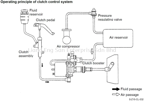
Operating principle of clutch control system When the clutch pedal and then the master cylinder are depressed, the boosting fluid will come from the master cylinder to the booster via pipe.
More Details...
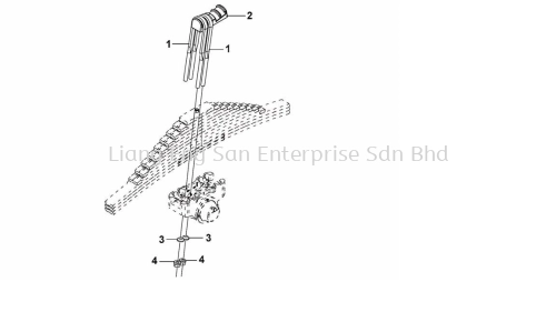
Equalizing suspension assembly parts 1. Balance shaft bracket 2. Straight grease nipple 3. Axle shaft 4. Axle tube 5. Relief valve 6. Fixing pin 7. O-ring 8. Internal thrust pad 9. End shim-balance bearing hub 10. Oil seal assembly 11. Balance bearing hub and bushing assembly 12. External thrust plate 13.
More Details...
DRIVE SHAFT WITHOUT INTERMEDIATE SUPPORT
Introduction of drive shaft structure
The function of drive shaft is to transmit the output torque and force from engine clutch to final drive.
More Details...
DRIVE SHAFT 2 WITH INTERMEDIATE SUPPORT
Introduction of drive shaft structure
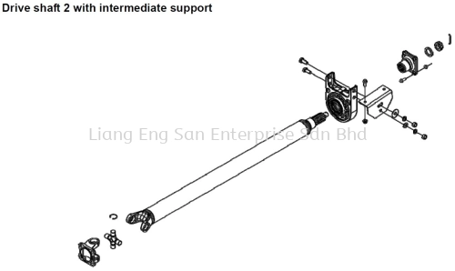
The function of drive shaft is to transmit the output torque and force from engine clutch to final drive.
More Details...
Introduction of drive shaft structure The function of drive shaft is to transmit the output torque and force from engine clutch to final drive.
More Details...
Introduction of drive shaft structure The function of drive shaft is to transmit the output torque and force from engine clutch to final drive.
More Details...
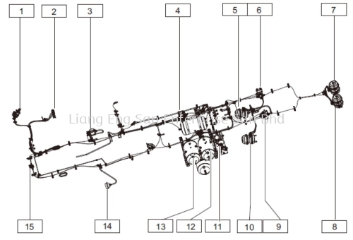
System Components Brake system layout 1. Series dual-chamber brake valve 2. Hand brake valve 3. Exhaust brake valve 4. Trailer brake valve 5. Rear right double diaphragm chamber assembly 6. Differential valve 7. Rear right double diaphragm chamber assembly 8. Rear left double diaphragm chamber assembly 9. Load sensing valve 10.
More Details...
Assembling Assembling Drawing of Rear Brake 1. Brake air chamber 2. Brake air chamber bracket 3. Grease nozzle 4. Camshaft bushing 5. Brake bottom plate 6. Oil seal 7. Camshaft 8.
More Details...
1. Plug 2. Lower dust cover 3. Roller 4. Brake bottom plate 5. Bushing 6. Oil seal assembly 7. Screw 8. Spring washer 9. Upper dust cover 10. Rivet 11. Brake friction plate 12. Brake shoe 13. Brake camshaft 14. Large return spring 15. Brake shoe shaft 16. Locking wire 17. Fastening screw 18.
More Details...
1. Elastic retainer ring 2. Brake adjuster 3. Cotter pin 4. Flat washer pin 5. U-fork 6. Flat head pin 7. Locking nut 8. Bolt 9. Spring washer 10. Spring washer 11. Bolt 12. Air chamber bracket 13. Camshaft spacer 14. Gasket 15. Front brake air chamber 16. Bolt 17. Spring washer 18. Rubber plug 19.
More Details...
 +6016-722 7757, +6016-722 9949
 info@lesesb.com.my


